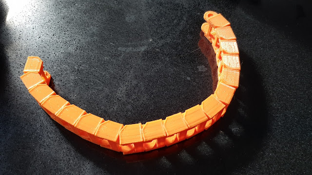
Update: connecting to the extruder carriage
One thing which I hadn't been able to decide upon was how best to get the cabling to the X carriage for the extruder and other elements. I had toyed with a cable from the gantry and this would be been fairly simple, but it would also leave quite a lot to be desired aesthetically. The other plan was to use cable chains to traverse the X and Z movement. This is a lot more fiddly, but is likely to give a much better result. It will, however, need quite a few more parts to be designed.
I decided that it would be worth a try to see how best to achieve this and I came up with a rough idea. To realise this, I needed a narrower chain than that which I'd used for the Y-axis (where the dimensions are less critical). So, I decided to simply scale the model I've used there to create a link 20mm wide.
I did this and left a large number printing to create a test chain. Unfortunately the scaling has also meant that the clearances were reduced too and I ended up with a chain which was very tight to assemble, stiff to move and to stiff to lay straight.
So, I have decided to bite the bullet and design a new link design from scratch. One thing I'd like to do is to get the bend radius as small as it reasonable in order to save space (and weight).
My present situation is trialling and printing a few links as I develop the design. Once I have working links I can then look at creating the mounts to configure two runs: one for X and one for Z and then joining them together.
In other developments: I have finally found a fanless 24V PSU to try. The one in the A8 Plus sounds like a hovercraft in full flight. There are quite a few fanless PSUs but none which can provide sufficient current. I think that I have found one on AliExpress. The good news is that it's less than £15. The bad news... it's less than £15. It remains to be seen whether/how it works, but in fairness the standard one is a cheap model, after all.


Comments
Post a Comment