Posts

Showing posts from August, 2020

Update: connecting to the extruder carriage

Image
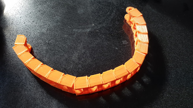
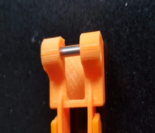
One thing which I hadn't been able to decide upon was how best to get the cabling to the X carriage for the extruder and other elements. I had toyed with a cable from the gantry and this would be been fairly simple, but it would also leave quite a lot to be desired aesthetically. The other plan was to use cable chains to traverse the X and Z movement. This is a lot more fiddly, but is likely to give a much better result. It will, however, need quite a few more parts to be designed.  I decided that it would be worth a try to see how best to achieve this and I came up with a rough idea. To realise this, I needed a narrower chain than that which I'd used for the Y-axis (where the dimensions are less critical). So, I decided to simply scale the model I've used there to create a link 20mm wide. I did this and left a large number printing to create a test chain. Unfortunately the scaling has also meant that the clearances were reduced too and I ended up with a chain which was ver

More mopping up and a delivery arrives!

Image
Despite having changed it already, I was still not altogether happy with the mount for my Y axis cable chain where it meets the bed. I had lowered it to accommodate the BL-Touch, but I then also replaced the glass bed with with a thinner magnetic PEI-coated flexy bed . This made the bed a millimetre or so lower which made me wince every time the BL-Touch headed in the direction of the connector.  So, I went back to the drawing board and completely redesigned the fixing, changing it from a single horizontal screw above the mount to a pair of shorter vertical screws and a thin clamp bar. I also tweaked the fitting by a millimetre to bring the mounting just a little nearer to the bed, now that the glass top is no longer there.  I moved from this To this new version Which now sits very flush, as can be seen here. Another change I made to it was to remove one small support bar at the rear. Although this provided some theoretical extra support across the mount, it  did mean that the 2mm or

Virtual Serial Connection to ESP-01s from Simplify3D over WiFi - Working!

Image
On my Creator Pro I have always liked to use a USB connection in order to manage and send prints, rather than the more conventional walk-up and plug in a card. I have a dedicated laptop which runs Windows 10 and Simplify 3D. Despite the perfectly valid criticism of updates stalling, I really quite like S3D and I do hope that the development does finally start moving again. For me, it's a very handy way of working. I can connect to the laptop from anywhere using Remote Desktop and run S3D as if I was local and slice and print - and manage the printer - all from one session. If I want to stop the job, I'm in direct control. A couple of webcams and I can see what's going on and set up and run things from anywhere. When I built the A8 Plus I simply added a USB hub and S3D will allow multiple sessions so that I can run both printers at once with the same facility as I had for one. On the new build, I have installed the ESP-01S WiFi module to the TFT35 to provide WiFi access to t

New release: Mount for TFT35 finally complete

Image
I have today completed the design of my mount for a Bigtreetech TFT35 V3 which I have chosen as the new touch display to replace the standard LCD.  I have been through a few iterations with this one (and then some) trying to get the size as compact as possible and the design as clean as I could. I'm really quite pleased with the results.  Read more about it in my information page here .  Although it's not yet fully released, I've also been tweaking the case design for the SKR 1.4 main board. Today I added a slot into the lid to fit the external EEPROM module I'm using. It's currently loose on a cable, but it now has a home (or will have when I've printed it).  Visit the main content pages

A day of two halves

Image
Well, it was one step forward, one step back today. Top of the list for the morning was to upgrade Marlin from the current 2.0.5.3 to 2.0.6. I had already downloaded the source files and got everything ready. I have quite a lot of customisation with the changes that I have already made, so I fastidiously worked through each in turn to make sure that the configurations matched.  On starting, there were a couple of glitches. One of these was a simple mistake where I'd forgotten to save the change to redefine one of the serial ports, so the TFT didn't connect. This was easily fixed with a quick change and recompile. Of more concern was the I2C connected EEPROM module. I could not get the new version to see it. It has been working fine under the current version, but nothing I tried could get it to work under the new one.  In the end, I threw in the towel and assumed that perhaps it's a bug. On that basis, I'd like to think that it'll get fixed at some point. I had simpl

Update: Mopping up

Image
Today I have been working on mopping up some tasks which need do in preparation for creating the cable looms. This latter task is now a little delayed as I've decided to make the stepper motor cables with shielded cables, just because I don't like the amount of noise which they're pumping out .  Today, I have carried out a number of preparatory and remedial processes.  Installed the ESP01 WiFi module into the TFT35 screen. I had had a number of aborted attempts at this previously (it's more than a little arcane) but this time I have managed to get it working. In practice, I may not use it that often but it could be useful in some circumstances. It does seem very basic, but it does mean that I'm not tied to a cable.  I also decided to replace the IGUS bearings on the X axis with traditional roller bearing ones. While I had the carriage apart, I also replaced the heater block, throat and nozzle.  I also upgraded the X axis belt to a high quality Gates one as I'd b

Behind the scenes

Image
You may be wondering how the new devices have been connected without a new mainboard as that stage isn't yet published. Well, the BTT SKR1.4 Pro has long since replaced the standard A8 Plus mainboard. However, it is still sitting on the table with cables hanging out of it as I test things. It may not be pretty, but... It is fitted into the case I have designed, has the EEPROM and DC-DC modules installed and is working. However, I intend to create a full cable harness for the project and can't really do that until the ancillary parts are in situ and working. I can then create a mount for the case. The case itself has a flange mounting system which will allow me to mount it in many orientations by having different brackets. I haven't yet published this side of things as, simply, I am waiting to complete it and as it is the heart of the system, it has to be fully correct.  Another element which has been running for some time are the custom endstop mounts. These were one of the

EMI. That's a lot of noise!

Image
I was working on the printer today and discovered that the steppers are pushing out huge amounts of EMI (electro-magnetic interference). I discovered this as I was trying to take a measurement with my calipers near to one of the motors and the figures were jumping all over.  I initially suspected a low battery but very quickly discovered that it is in fact interference from the motors and their cables.In fact the interference is so marked that even moving the calipers, powered off,  close to a motor will force them to switch on and cause numbers to flash.  Pick a number I have also noticed that there is an effect too to the TFT screen. It works, but if I go into a setting for something like temperature while a print is running then the figures there jump up and down too. This is only apparent since I have moved to the new, longer cables and moved the unit itself, which is logical.  I'm obviously going to need to add creating shielding to the to-do list.  Visit the main content page

Update: Nearly there with the TFT35 mount

Image
I've been tweaking the design and playing with making it as small as possible and I think that I'm now at (or very close) to the final prototype. I have to slightly modify the fascia (which I'm printing now) and then perhaps look at adding some aesthetic embellishments to the front. It's a very snug fit and every slots together neatly and is fixed with recessed M3 screws.  I am quite pleased with how the mounting bracket worked out. I have managed to incorporate the cable exit and cable clamping into the single part, which is quite elegant I think. The cable exit is completely covered by the bracket and it redirects the cables downwards through a single tidy slot.  Visit the main content pages

Bed levelling woes

Image
One of the effects I have noticed during testing is that although I now have ABL set up and (seemingly) working, it doesn't seem to be as accurate as I'd expected. I have analysed the mesh and the right side of the bed is slightly lower than the left. By watching the printer I can see that the Z axis is certainly moving during a single layer of a print, so something is clearly happening.  Despite this, the print quality is very poor on the right side, whereas the left is very good.  Left side of bed Right side of bed To te st this further, I created a test model (I know that there are hundreds, but I couldn't find one which was quite right for what I wanted) and printed that several times. Each time, the right (lower) side of the bed was printing with much poorer quality than the left.  My test model My first thought was that perhaps my Z steps/mm were wrong and the printer was simply not moving the correct amount. I re-calibrated and tested this twice, but everything seeme

To do: Create Neopixel power injector

Image
When I bought the Neopixel strips for my light bar , I bought three different densities: 30, 60 and 144 LEDs per metre in 0.5m lengths. There is about a 30 LED limit on the LEDs which the SKR1.4 mainboard can support. So, I used the 30pm for testing as there were only 15 LEDs there and then built the light bar with the 60pm ones and managed to fit 19 into the bar.  Neopixel Strips in 30, 60 and 144 pm In theory, I could get a greater light density (and higher brightness if needed) by using the 144pm and that would give me around 47 LEDs. However, this would draw too much current from the mainboard.  The obvious option is to use a separate PSU for the 5V rail on the Neopixels and use only the Data line from the mainboard. To do this I need a cheap buck converter to output the 5V directly from a 24V feed from the PSU.  So, the project will be: Order an appropriately (c3A) rated converter (this I have done, from Ali Express) Create a case to mount to the chassis Modify the wiring harness

Design Process

Image
  I have just created a page where I discuss the design process I'm following to complete this project It's not without its costs in terms of failed attempts, but I am determined to get to the best design for each element!  Please see the specific page  here .  Visit the main content pages

WIP: Case for BTT TFT35

Image
I'm currently working on a case for my TFT35 (see video) including the following features Easy to print - minimal support Adjustable angle and optional mounts Cable support I'm also working on a slight rework to my LED diffuser to have two variants. The other was good, but the adhesive on the Neopixel strip failed, so I'm redesigning it to have two snap-together parts to allow glue to be used directly.  Visit the main content pages

Fitted new magnetic PEI removable bed and low profile Y axis adapter

Image
It's not innovative, I know, but I have finally got around to fitting my removable PEI flex bed. I have one on my Creator Pro and it's very impressive and makes print removal very simple.  They are quite expensive for a bed the size of the A8 Plus, but the seller (Energetic 3D) on Ali Express was having a sale, so I grabbed one while they were (a little) cheaper.  While the bed was apart I finally had an opportunity to fit the updated mounting bracket for my Y axis cable chain.The previous one has perfomed very well but it was a little too high for my BL-Touch mount. So I modifed the design to create a low profile version which the BL-Touch misses.  It'll be interesting to see how the PEI performs. I'd like to think that it'll be as good as the Creator Pro. I have one which has smooth PEI on one side and powder coated on the other (as in the photo).  Visit the main content pages

New release: LED light bar and diffuser

Image
I have now completed the design and testing of my gantry light bar. This uses a Neopixel strip and mounts to the gantry using a new design. The mounting brackets incorporate both routing and tie bases to make cable exit simple and secure. See more information on my release page , or download the model from Cults 3D . Please let me know your thoughts in the comments.  Visit the main content pages

To do: Nozzle illumination idea

Image
 While working on the NeoPixel fixing on the gantry, I was puzzled by why the first LED only, remained on and white. It wasn't until I was browsing the Marlin code that I spotted this I couldn't see that this was going to be of any use but then realised that I could split the run of LEDs and have this first one installed for nozzle illumination, separate to the main run on the gantry. So, I plan to add this to the to-do list. I can fairly easily modify my BL-Touch mount too such that the LED can be mounted there, directed at the nozzle but far enough away to avoid the heat. I just need to include the extra wiring in the harness.   X marks the spot I can then reference this LED separately in GCODE to control the nozzle illumination as I need. Visit the main content pages  

WIP: Mount and diffuser for LED light bar.

Image
I am currently working on installing some NeoPixel LEDs on to the printer and this will need a mounting and diffuser. So, I drew up a quick design and it printed very well first time. This is my first "real" print since installing the BL-Touch and I'm sure that I wouldn't have been able to print something this long (330mm) this easily before it was in place, due to the uneven nature of the bed.  This is currently using a test strip of LEDs and held with tape as I work on the brackets. It's currently printed in white PLA, but I'm going to test transparent PETG too. Visit the main content pages  

New release: BL-Touch mount

Image
I have now completed the development and testing of my solution for a BL-Touch mount. It is working well and is a good solid mount.  Please visit the relevant build page for more details.  You can download the model from Cults 3D . Visit the main content pages

WIP: BL - Touch mounting bracket: easy print, easy installation

Image
I'm currently working on a design for a BL-Touch mount. This is just proof-of-concept at this point, but I hope that it will work as planned and integrate well with the other parts The concept is to design something which is easy to print and easy to install. Importantly I didn't want something which interferes with the fans (which other designs I've found seem to do). Visit the main content pages

SKR1.4 and TFT 35 - using long file names and print from SKR SD card

Image
This is a bit of a diversion from the rest of the blog, but it's relevant as it's on the same path. I felt it might be helpful to post this as I'd tried, unsuccesfully, to find a definitive answer elsewhere so got there by trial and error.  If you have an SKR 1.4 mainboard coupled to a BTT TFT35 (NB I suspect that this will also be relevant to other combinations of MB and TFT) and want to Enable long filename support Add the MB SD card as a print source This is what I had to do to get this working. There are two areas which need to be changed  CONFIG.INI on the TFT CONFIGURATION_ADV.H on the Marlin (2.X) build This solution is based around my configuration but is likely to be more generic, I think. I am running SKR 1.4 Turbo - Marlin 2.0.5.3 BTT TFT35 V3.0.26 Change Marlin Firmware You will need to create a new build, with the following changes in the configuration_adv.h file. First, you need to enable the onboard SD card as Then, to enable the long filenames change:  Remo

My first benchy along the way

Image
 I thought that while I'm tuning things I should try printing a benchy just to see how far off things are. Not too far, it seems. Not that it's in any way perfect but it's certainly not as bad as I'd expected. There is some stringing, but I've not even touched retraction. This was more or less a default S3D PLA profile. So, on to the next bit: a mount for a BL-touch which won't interfere with my cleaning station Visit the main content pages

What a difference a day makes!

My new rods and bearings arrived to replace those on the Y axis. It turned out to be one of those cases where you don't know how bad something is, until you replace it. The movement on the Y axis, while not perfect, is so much smoother. I'm now on to running some acceleration and junction deviation tuning as a test.  Ignore the print quality, I'm just looking for limits for now. However, the Y axis motion is very much smoother already.  I had to buy 500mm rods and use an angle grinder to cut and smooth the ends, but they seem to fit fine. I now also have some further ideas about improving the rigidity of the idler mounts though, as there is still some flex there which I'd like to remove.  Visit the main content pages

Coming soon: Housings for X, Y and Z smoothed limit switches

Image
A large part of this project has been replacing the main board with a BTT SKR1.4 Pro (of which more soon). I wanted to start this using good quality limit switches rather than sensorless, for various reasons. As one would expect, the standard limit switches on the A8 Plus are cheap components with no smoothing; just raw switches. The new main board requires proper smoothed switches and these are a much better solution anyway. Z axis Limit switch case So, I have spent quite some time designing adjustable housings for switches for all three axes. These have been working well and I plan to release these shortly. Each can be adjusted where necessary and also incorporate cable management to keep things tidy and constrained.  The Y axis mount uses a modified actuator on my Y axis belt clamp .  Visit the main content pages

Y axis finally grinds to a halt (literally!)

Image
I have written before about how one of the failings in the A8 Plus are the quality of the bearings and linear rods. I have already had to replace the ones on the X axis , using polymer bearings rather than roller. Well, during some further testing yesterday I started to get huge Y axis layer shifting. On investigation I could see that the Y axis had all but seized.  A little while ago I'd noticed it was binding a little with the IGUS bearings in place, so I'd changed back to convention LM8UUs to test. This is what happened to the rods Not the clearest of pictures, perhaps, but you can probably see the striations (gouges would be more accurate) along the length of the rods. So, I now have new hardened rods and good quality bearings on order and will replace these as soon as they arrive.  The A8 plus uses rods which seem to be 442mm long. So that's going to mean some fun times cutting down 500mm rods.  Visit the main content pages

New Release: Nozzle cleaning station

Image
I have now completed the testing of my nozzle cleaning station and have released the model and completed the information page on this.  The design is a single bracket which takes a cheap copper brush head and allows you to fully automate a wipe of the nozzle on the A8 Plus. To read more about this, please visit the information page here .  Visit the main content pages