Posts

Showing posts from September, 2020

Update: Back together, but there's that noise...

Image
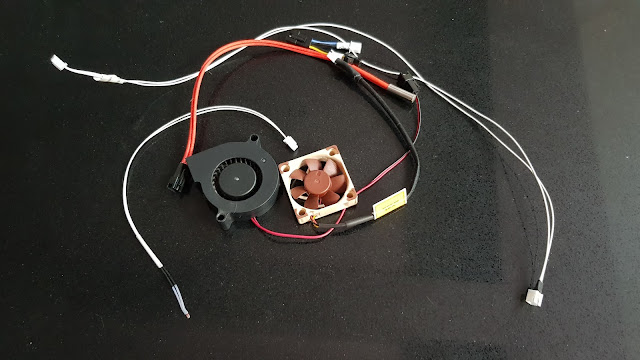
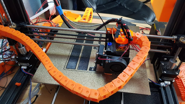
So, I had completed the cabling in the chains and they were ready to put to the test. I connected all of the connections at each end and powered on. I had full X and Z movement and everything seemed OK.  So, after redoing basic calibrations, I started a test print. Everything seemed OK and then suddenly there was a loud ticking noise. I traced this to what I thought was the X stepper. It seemed too high-pitched to be it skipping steps, but it was certainly there and it was only making the noise under X movement.  So, I tweaked the X motor current up a smidge - to no avail. Annoyingly, it wasn't happening all of the time, the printer seemed to home and perform levelling without a problem, but it would randomly start when printing. I wondered whether the changes had caused something to seize on the carriage, so I loosened the belt and moved the carriage. It moved fine.  I re-tightened the belt and tried again. The problem persisted. On listening more closely, it actually sounded more

Update: new BL-Touch mount with nozzle LED

Image
Today I have been working on installing the final cables into the chains. Having everything demountable was a lot more work, but it will make later changes and upgrades far simpler.  I started by creating the LED mount itself This takes a single Neopixel LED and connects a 5V power feed and data in and out. The 5V is already on the carriage and so, now, is the Neopixel data. This mounts to the modified BL-Touch mount as The other side of the mount now has low-profile cable routing included for both the new LED and the BL-Touch cabling The modified mount uses the same fixings as the original - to the rear of the carriage. I then needed to modify Marlin to increase the number of LEDs from 46 to 47. The other change is to add the facility to have a static Neopixel LED The cabling in the chain is now complete and it needs to be re-attached to the newly modified carriage mount. I have also been adding clear labelling to each of the cables so that they make sense in a few months' time. O

Update: Still at it, but getting closer

Image
I'm a little busy with family things at the moment, but have managed to find some time to move forward, nonetheless. I am still working on cable tidying and routing for the cable chains. I have added additional cable fixings to the carriage end of the chain mount. This will allow me to better hold the flying leads at the carriage end more securely. Similarly to this, I have also created a modified fan cover for the new Noctua cooling fan on the extruder. This includes a pair of cable clips to securely route the cable up to the chain mount.  I have also now completed the shielded stepper cable for the X-axis motor, to add to the extruder motor cable which I installed a little while ago.  It installs to the motor as normal, with a flying earth lead (currently not connected as can be seen).  At the other end, it joins the extruder cable in the 20-way connector So, things are slowly coming together and just need reconnecting. I only need to make one more cable to go into the chains, wh

Update: Testing and cable tidying

Image
I have now completed the cabling to the extruder carriage (except, see below) and have tested each part successfully. This has included a 5V feed for the Noctua fan which I have now installed. All of the parts seem to be working well. This includes the new shielded stepper cable which is now in place for the extruder motor. The other end of the cable goes into four positions in a 20-way socket and plug. This seems to work well and I can now create a similar cable for the X axis motor which will be the final element to connect through the new cable chains. All of the steppers will then terminate in this connector, allowing all to be removed if needed and for the shielding to be earthed at this common point. I am now left with a lot of cables and connectors on the carriage for which I am having to create mounts. For example, my BL-Touch mount has been modified to create built-in ribbon cable slots, to hold the cables more flushly than with the original cable tie base which was a little p

Update: Cables, cables everywhere... and a new PSU

Image
Today has involved a lot of cable loom making and splicing of existing cabling. My plan is to have each part modular. So, the cabling within the cable chains will have terminations at each end. There will then be link cables from the mainboard case to link at the bottom of the Z axis chain. At the X carriage there will then be separate connectivity for  Heater Thermistor Cooling fan Part cooling fan BL-Touch The picture shows spliced connections for these. The exception to this will be the stepper itself which will connect directly to the motor at the carriage end. At the mainboard end, all of the steppers will terminate into a single pair of twenty-way connectors. This will allow a single unplugging of all of the steppers. There will also be an earth point which will connect into the shield on each of the stepper cables to provide shielding of the cables. It will also connect to the body of each motor. to quieten that.  My aim is to have the entire mainboard case  demountable so as to

Update: Started on cabling - and intolerant drawers

Image
I have now been running my combined X and Z axis cable chains for a while in testing, without any cables installed. This has been successful, so I wanted to start on creating the cable looms to replace the old (and very poor) umbilical.  One thing with the cable chains which was a little irritating was that there was a slight sag to the X axis chain due to its length and weight. While this wasn't really a problem, it was a itch which needed scratching. To create a simple resolution, I modified the design of the carriage mount an introduce a ten degree tilt to it, to offset the sag. This was a very simple solution and it seems to have worked.  By tilting the chain ever so slightly against the direction of sag, it has straightened it at the lowest point.  The next exercise was to create the cable looms. My ideal is to have each component on the carriage removable. I did toy with using a single connector for this, but the mix of currents and types made me decide against it. Moreover i

Update: Where there's smoke...

Image
Today I have been working on preparing things for the weekend's upgrades.  The next batch of components are printing for the left of the two storage drawers. You can also see the X axis cable chain which is the high priority for the weekend: to move the cabling into it.  I also received the following delivery today It's a wireless smoke alarm. It functions exactly as a normal smoke alarm, but also links into a Sonoff bridge. This means that I can create a very simple power kill on the printer in the event of smoke. I have just installed one on my Creator Pro too (which has had a conventional smoke alarm for some time) and it seems to test well. I trip the smoke alarm and the printer powers off almost immediately. It's not foolproof, of course, but it's certainly far better than not having it.  I have also created a simple bracket concept, with a cover, to mount it on the Z-axis gantry. The other thing I've been looking at today are Z axis pull rods. These will help

Imminent release: Storage trays are finished

Image
Well, after some ado I have finally completed my storage tray solution. It's in numerous parts in order to remove the significant number of supports it would have needed and the parts just slot together. The whole thing then screws into the frame slots.  It also includes clips for the display ribbon cables.  These parts... Slot together like this. To be installed like this To do this I plan to make this available for download soon.  In other news: I have had another delivery from AliExpress as Which is an automatic case cooling kit. It has a built-in thermistor and will take 24V in and be used for the case for my SKR main board. This means that the fan will only come on when it's needed - part of my silencing scheme. I'll probably replace the fan with a Noctua to help further.  Visit the main content pages

Update: Today I are been mostly...

Image
Today I have been working on a few tweaks. I have now (I think) finally completed the design for my storage trays. It now has more parts than Alec Guiness in Kind Hearts and Coronets (Eddie Murphy in the Nutty Professor, for younger readers), but everything clips together to provide for the strongest print with the minimum of supports. This should mean that it will use less material and still provide for a strong assembly.  I came up with this joint for one of the corners. It comprises three lugs which can be printed vertically.  Which fit into three corresponding slots and then locked into place by sliding along This then provides a very tight and firm corner fixing meaning that each corner can be printed in its own optimum orientation and removes the need for supports.  It's a very simple, but very positive and firm fit. Obviously these are sample cut-down panels to test the joint. I plan to print the final version of the final part for this tomorrow and install the first of the

Sneak Peek: X and Z axis cable chains

Image
I've been asked on Reddit for a sneak peek at the prototype of my combined X and Z axis cable chains. Well, they are now fitted in a test configuration and here are some pictures and a brief video. The cables aren't actually in it yet as I'm just testing the motion, but things are looking promising at the moment.  These are the chains at present (the Z axis is a little long still). Below is a video of them in motion  They still need some tweaking, but things seem to be working and if I can get rid of the awful umbilical that's there by default, I will be pleased. I just need to create the appropriate cabling. I'm not happy with the dupont connectors on the BL-Touch, for example. They're just screaming to fall apart, so will be replaced with some JST XH inline connectors.  Visit the main content pages

Sensorless homing and musings on Z-offset

Image
In a perfect example of irony, I have just decided to try sensorless homing - just a few days after finally having got around to releasing my designs for smoothed endstops .  The process turned out to be quite simple. I had some spare 2209 stepper drivers as the originals had had their diag pins removed in order to use the endstops. In fact, I had desoldered these rather than cutting them and even retained the pins, so I could also have simply resoldered the pins back into place. But, as I had the spare drivers, it seemed unnecessary.  Once the new drivers were installed, there were just a couple of changes to the Marlin firmware which I needed to make.  First was a change to enable the sensorless homing and to set default stall sensitivities.  The next change was to change the Endstop Inverting to false for the X and Y axes. Effectively, telling Marlin to ignore the endstops. I compiled a new version of the firmware and then installed it to the printer. Thereafter, it was necessary to

Update: proof of concept

Image
Today, I have been working on the mounts for the X and Z axis cable chains. I printed prototypes of each and tested their fit. I then installed some test chain into each to check alignment and fit.  The central mount which consolidates the two axes is by far the more complex of the two. The fit wasn't quite there yet (as you can see in the photo) in terms of the alignment with the stepper mount, but the size and alignment of the chain mounts seems to be spot on. So, I can now take this prototype, tweak the measurements and then print a new candidate. In fact, what I will do is print a template alignment section of the model, cutting out all of the element except for the critical points. This means that I can print the template quickly and lay it over the motor in situ. This will significantly speed up the process.  The carriage mount prototype was more successful. It seems to have fitted perfectly first time. It is in two parts to allow easy assembly and to allow the extruder to be

Design Updates

Image
This weekend I'm hoping to forge ahead with my solution for the X and Z axis cable chains. I am now printing prototype mounts and then I will start testing. I think that I will set up the X axis on its own first, using existing cabling and then, if that's succesful, add in the Z too which will need rewiring.  This is my concept design for the bracket which will link the X and Z axis chains. I have now printed a first prototype as It's printed quite well. so I now need to tweak the measurements to make it fit perfectly. I also have completed the concept design for the X carriage mount for the other end of the X chain. I've designed this in two parts to make it easier to fit and to limit the possibility of it making access to the extruder difficult. It means that it can just be unscrewed if it's needed to be removed. I'm also toying with extending it and adding a filament guide, as it is effectively sitting above the extruder motor.  This part is printing now.  In