Posts

Showing posts with the label LED

Update: new BL-Touch mount with nozzle LED
Image
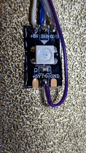
Today I have been working on installing the final cables into the chains. Having everything demountable was a lot more work, but it will make later changes and upgrades far simpler.  I started by creating the LED mount itself This takes a single Neopixel LED and connects a 5V power feed and data in and out. The 5V is already on the carriage and so, now, is the Neopixel data. This mounts to the modified BL-Touch mount as The other side of the mount now has low-profile cable routing included for both the new LED and the BL-Touch cabling The modified mount uses the same fixings as the original - to the rear of the carriage. I then needed to modify Marlin to increase the number of LEDs from 46 to 47. The other change is to add the facility to have a static Neopixel LED The cabling in the chain is now complete and it needs to be re-attached to the newly modified carriage mount. I have also been adding clear labelling to each of the cables so that they make sense in a few months' time. O...

Update: Testing and cable tidying

Image
I have now completed the cabling to the extruder carriage (except, see below) and have tested each part successfully. This has included a 5V feed for the Noctua fan which I have now installed. All of the parts seem to be working well. This includes the new shielded stepper cable which is now in place for the extruder motor. The other end of the cable goes into four positions in a 20-way socket and plug. This seems to work well and I can now create a similar cable for the X axis motor which will be the final element to connect through the new cable chains. All of the steppers will then terminate in this connector, allowing all to be removed if needed and for the shielding to be earthed at this common point. I am now left with a lot of cables and connectors on the carriage for which I am having to create mounts. For example, my BL-Touch mount has been modified to create built-in ribbon cable slots, to hold the cables more flushly than with the original cable tie base which was a little p...

Update: Bits and bobs

Image
Today I have been doing various things to prepare for some work at the weekend. I'm hoping to install the upgraded LED bar, so I spent some time earlier in the day trying to get the diffuser to print in PETG.I got very close, but as it's only 0.4mm thick with a lot of bridging, it wasn't quite there. I shall probably try again just because it's a challenge. I think that if I push the extrusion multiplier up a notch, I may get there. I printed a new base successfully, but the diffuser is very thin indeed and it has only one extrusion width to hold to the bed too.  In my defence, the photo shows the print after I deliberately overflexed it to see how much give it had. It's now on my to-do list (under "printing challenges"). In the meantime, I can continue with the PLA version.  In order to get to power to the new DC-DC converter, I need to splice the 24V rail. I thought that using some lever connectors would be nice, so I've been prototyping a mount for ...

To do: Create Neopixel power injector

Image
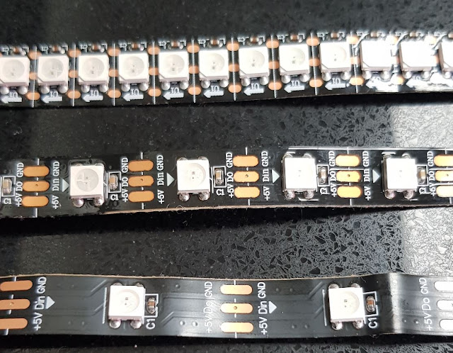
When I bought the Neopixel strips for my light bar , I bought three different densities: 30, 60 and 144 LEDs per metre in 0.5m lengths. There is about a 30 LED limit on the LEDs which the SKR1.4 mainboard can support. So, I used the 30pm for testing as there were only 15 LEDs there and then built the light bar with the 60pm ones and managed to fit 19 into the bar.  Neopixel Strips in 30, 60 and 144 pm In theory, I could get a greater light density (and higher brightness if needed) by using the 144pm and that would give me around 47 LEDs. However, this would draw too much current from the mainboard.  The obvious option is to use a separate PSU for the 5V rail on the Neopixels and use only the Data line from the mainboard. To do this I need a cheap buck converter to output the 5V directly from a 24V feed from the PSU.  So, the project will be: Order an appropriately (c3A) rated converter (this I have done, from Ali Express) Create a case to mount to the chassis Modify the w...

To do: Nozzle illumination idea

Image
 While working on the NeoPixel fixing on the gantry, I was puzzled by why the first LED only, remained on and white. It wasn't until I was browsing the Marlin code that I spotted this I couldn't see that this was going to be of any use but then realised that I could split the run of LEDs and have this first one installed for nozzle illumination, separate to the main run on the gantry. So, I plan to add this to the to-do list. I can fairly easily modify my BL-Touch mount too such that the LED can be mounted there, directed at the nozzle but far enough away to avoid the heat. I just need to include the extra wiring in the harness.   X marks the spot I can then reference this LED separately in GCODE to control the nozzle illumination as I need. Visit the main content pages