Posts

Showing posts with the label Cabling

New release: X and Z axis cable chains
Image
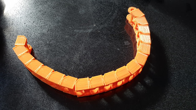
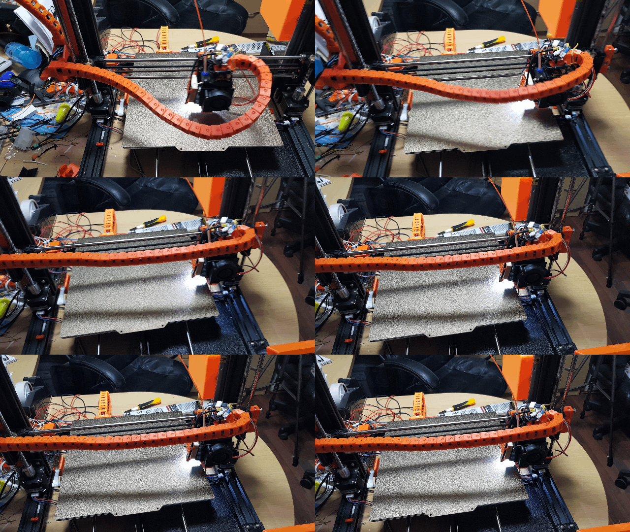
I have finally completed the release of these combined cable chains. This has been something of a passion project for me as the original X carriage umbilical was one of the areas of the system which I really didn't like. It was either too short or too long or would get in the way of the print.  This particular design has taken quite some time as I had some very specific requirements which meant that I had to design each element from scratch. This included the chain links for which I had a number of requirements Easy to print No supports needed 20mm wide to match extrusion on Z axis Removable and replaceable in situ I have managed to achieve all of these goals with my design, I believe. The links are then used to create the two chains, connecting via custom mounts at the base of the Z axis, the top of the X carriage and joined together in a dual-axis bracket mounted against the X axis stepper.  For more information, please see my blog page on this project element.  The mo...

Update: X and Z axis chains and storage drawers

Image
This is a brief update and progress and information about a new release of the X and Z axis cable chains and the real (finally) release of the storage drawers. To the last point first: I took some further measurements and the problem I had with fitting a pair of drawers side by side as they were designed was not at all due to tolerances, as I'd first thought, but rather because of some significant dimensional inaccuracies in my first test build. In hindsight, the print was done quite early in the build, before I'd tuned very much at all. So, I hope to release the drawers very soon after the false start before.  Similarly, I'm just creating a time-lapse of a print to demonstrate the new cable chains in use in earnest. I plan to release this alongside the models themselves very soon too. Another thing I have now been able to do is connect the fanless PSU. Not that it should be a huge surprise, but the difference in noise levels is very significant indeed. The fan in the stand...

Update: new BL-Touch mount with nozzle LED

Image
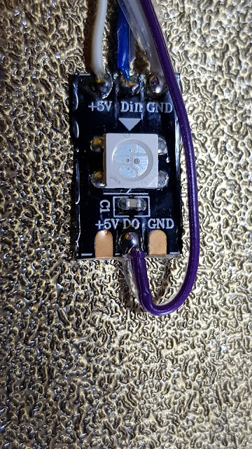
Today I have been working on installing the final cables into the chains. Having everything demountable was a lot more work, but it will make later changes and upgrades far simpler.  I started by creating the LED mount itself This takes a single Neopixel LED and connects a 5V power feed and data in and out. The 5V is already on the carriage and so, now, is the Neopixel data. This mounts to the modified BL-Touch mount as The other side of the mount now has low-profile cable routing included for both the new LED and the BL-Touch cabling The modified mount uses the same fixings as the original - to the rear of the carriage. I then needed to modify Marlin to increase the number of LEDs from 46 to 47. The other change is to add the facility to have a static Neopixel LED The cabling in the chain is now complete and it needs to be re-attached to the newly modified carriage mount. I have also been adding clear labelling to each of the cables so that they make sense in a few months' time. O...

Update: Still at it, but getting closer

Image
I'm a little busy with family things at the moment, but have managed to find some time to move forward, nonetheless. I am still working on cable tidying and routing for the cable chains. I have added additional cable fixings to the carriage end of the chain mount. This will allow me to better hold the flying leads at the carriage end more securely. Similarly to this, I have also created a modified fan cover for the new Noctua cooling fan on the extruder. This includes a pair of cable clips to securely route the cable up to the chain mount.  I have also now completed the shielded stepper cable for the X-axis motor, to add to the extruder motor cable which I installed a little while ago.  It installs to the motor as normal, with a flying earth lead (currently not connected as can be seen).  At the other end, it joins the extruder cable in the 20-way connector So, things are slowly coming together and just need reconnecting. I only need to make one more cable to go into the ...

Update: Testing and cable tidying

Image
I have now completed the cabling to the extruder carriage (except, see below) and have tested each part successfully. This has included a 5V feed for the Noctua fan which I have now installed. All of the parts seem to be working well. This includes the new shielded stepper cable which is now in place for the extruder motor. The other end of the cable goes into four positions in a 20-way socket and plug. This seems to work well and I can now create a similar cable for the X axis motor which will be the final element to connect through the new cable chains. All of the steppers will then terminate in this connector, allowing all to be removed if needed and for the shielding to be earthed at this common point. I am now left with a lot of cables and connectors on the carriage for which I am having to create mounts. For example, my BL-Touch mount has been modified to create built-in ribbon cable slots, to hold the cables more flushly than with the original cable tie base which was a little p...

Update: Cables, cables everywhere... and a new PSU

Image
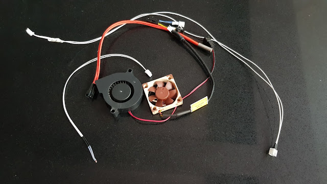
Today has involved a lot of cable loom making and splicing of existing cabling. My plan is to have each part modular. So, the cabling within the cable chains will have terminations at each end. There will then be link cables from the mainboard case to link at the bottom of the Z axis chain. At the X carriage there will then be separate connectivity for  Heater Thermistor Cooling fan Part cooling fan BL-Touch The picture shows spliced connections for these. The exception to this will be the stepper itself which will connect directly to the motor at the carriage end. At the mainboard end, all of the steppers will terminate into a single pair of twenty-way connectors. This will allow a single unplugging of all of the steppers. There will also be an earth point which will connect into the shield on each of the stepper cables to provide shielding of the cables. It will also connect to the body of each motor. to quieten that.  My aim is to have the entire mainboard case  demoun...

Update: Started on cabling - and intolerant drawers

Image
I have now been running my combined X and Z axis cable chains for a while in testing, without any cables installed. This has been successful, so I wanted to start on creating the cable looms to replace the old (and very poor) umbilical.  One thing with the cable chains which was a little irritating was that there was a slight sag to the X axis chain due to its length and weight. While this wasn't really a problem, it was a itch which needed scratching. To create a simple resolution, I modified the design of the carriage mount an introduce a ten degree tilt to it, to offset the sag. This was a very simple solution and it seems to have worked.  By tilting the chain ever so slightly against the direction of sag, it has straightened it at the lowest point.  The next exercise was to create the cable looms. My ideal is to have each component on the carriage removable. I did toy with using a single connector for this, but the mix of currents and types made me decide against it. ...

Update: proof of concept

Image
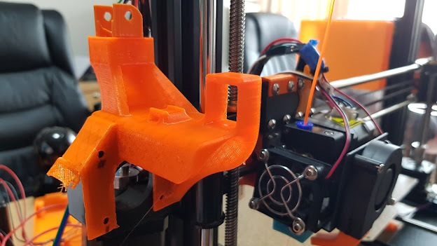
Today, I have been working on the mounts for the X and Z axis cable chains. I printed prototypes of each and tested their fit. I then installed some test chain into each to check alignment and fit.  The central mount which consolidates the two axes is by far the more complex of the two. The fit wasn't quite there yet (as you can see in the photo) in terms of the alignment with the stepper mount, but the size and alignment of the chain mounts seems to be spot on. So, I can now take this prototype, tweak the measurements and then print a new candidate. In fact, what I will do is print a template alignment section of the model, cutting out all of the element except for the critical points. This means that I can print the template quickly and lay it over the motor in situ. This will significantly speed up the process.  The carriage mount prototype was more successful. It seems to have fitted perfectly first time. It is in two parts to allow easy assembly and to allow the extruder ...

Don't you just hate it when...

Image
The main plan for today was to start printing the new cable chain. I set up the print for 40 sets Everything seemed to be going very well until... There was a nasty snapping noise and I saw that the filament had broken. Luckily I spotted it before the loose end disappeared into the extruder. I managed to pause the job and replace the filament, until... There was another snap as one of the prints broke loose and the whole spool of filament looked like an ugly macramé experiment. I paused the job again, stuck down the loose print with tape and spent about five minutes untangling the filament.  I restarted the job and everything was fine, until... a whole raft of other prints then detached themselves and went pinging around the room. This time I decided that pausing wasn't helping, so I cleared out the loose prints as best I could while it continued and let it carry on, waiting to see how many good prints I'd get. It's still running as I write.  Oh, did I mention that this all...

Update: connecting to the extruder carriage

Image
One thing which I hadn't been able to decide upon was how best to get the cabling to the X carriage for the extruder and other elements. I had toyed with a cable from the gantry and this would be been fairly simple, but it would also leave quite a lot to be desired aesthetically. The other plan was to use cable chains to traverse the X and Z movement. This is a lot more fiddly, but is likely to give a much better result. It will, however, need quite a few more parts to be designed.  I decided that it would be worth a try to see how best to achieve this and I came up with a rough idea. To realise this, I needed a narrower chain than that which I'd used for the Y-axis (where the dimensions are less critical). So, I decided to simply scale the model I've used there to create a link 20mm wide. I did this and left a large number printing to create a test chain. Unfortunately the scaling has also meant that the clearances were reduced too and I ended up with a chain which was ver...